How to Connect and Mount RF Connectors?
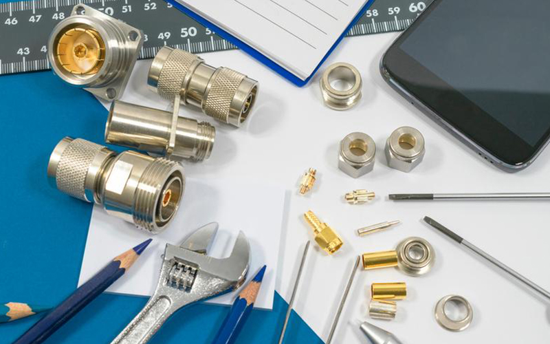
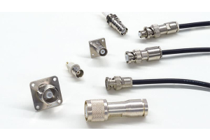
Connectors in electronic equipment play the role of a bridge, connecting circuit boards, cables and equipment closely to ensure the stability of signal transmission and the reliability of the overall performance of the equipment. Different types of connectors and their installation methods have their own advantages and applicability in different application scenarios. This article will introduce the connection and installation methods of common RF connectors.
Connection of RF Connectors
1. Threaded Connection
Threaded connections are a slow but reliable method of connection and are particularly suitable for use in environments subject to severe vibration. Using connector series such as SMA, TNC, N, UHF, SMC,DIN 7/16 and DIN 4.1/9.5, threaded connections ensure a more stable connection. This type of connection is used in areas such as test equipment, military and telecommunication equipment. The threaded connection consists of a thread on the connector and a nut. Special attention must be paid to the maximum permissible torque and clamping force of the thread.


SMA Connector RP Jack


BNC Connector Jack
2. Bayonet Connection
Bayonet connections are used in scenarios where reliable and fast plugging and unplugging is required, mostly in test equipment and military equipment. Common connectors include BNC, BNT, SHV, and MHV. The disadvantage is that contact is less reliable when subjected to vibration. The shaking effect reduces transmission performance.
3. Snap-On Connection


MCX Connector Jack


DIN 1.0/2.3 Connector Jack
4. Push to Self-Lock Connection
This connection mechanism has a unique self-locking method with insertion and removal speeds similar to the push-in connection method, but is very reliable in the self-locking state. It will not unlock even if the cable is pulled. Quick-lock connections are typically used for small connectors in high-density installations, such as DIN 1.0/2.3 and DIN 1.6/5.6 series, which can be inserted and removed quickly and remain reliably locked.
5. Slide-In Connection
The slide mechanism is used extensively where ahigh packing density is needed. A typical application is the interconnection of daughterboards to mother boards. The disadvantage ofthis kind of coupling style is its reduced reliabilityand thereby its lower quality relative to threadedconnections. On the other hand easy handlingcan compensate for this.


Cable Mount
Common RF connector cable mounting methods include crimp , solder.
Crimp
A crimp connection is where the metal ferrule of a connector is attached to the conductors of a cable by pressure and force. This usually requires the use of a specialized crimping tool, which ensures a good electrical connection by pressing the metal ferrule of the connector against the cable. This is suitable for scenarios where a quick connection is required, but the quality and consistency of the crimp connection depends on the skill and experience of the operator.
Solder
This is a common way of mounting connectors and is particularly suitable for applications where a solid connection is required. In this method, the metal part of the connector is connected to the conductor of the cable by soldering or welding. This method is suitable for applications that require high signal transmission and stability, such as military and aerospace applications. However, once soldering is completed in this method, the connector is difficult to replace and is suitable for fixed wiring.
Panel Mount
There are several common installation methods for panel mounting: bulkhead mounting, flange mounting, sealed construction and field replaceable fixing.
Bulkhead mount: Suitable for through-wall fixing, where the connector is secured by a thread. This technique allows the connector to pass through the panel and is often used where protection against vibration is required. The advantages are that it is cost effective and the connectors are interchangeable.
Flange mount: Only one side of the panel can be secured by the connector. The center hole is unthreaded only for the inner conductor or shell to pass through. This is more expensive compared to bulkhead mounting, but is equally interchangeable.


Sealed Construction: Is a variation of the flange mounting method. The inner conductor of the connector is sealed in a full glass housing, the housing is threaded in place, and the connector will then be soldered to another unit. This means that the soldering process follows the installation and the connector cannot be replaced once it has been soldered. This method is generally used indoors and where soldering equipment can be applied.
Mounted on PCB


Through-Hole Mount: The connector pins are pressed into the holes of the PCB board. Through-hole mounting guarantees the same electrical and mechanical properties as the traditional soldering method, but it is much easier to install.
Solder: Suitable for three different types of connectors: connectors with soldered pins, surface mount connectors and plug-in mounts that require soldering. Soldering is similar to through-hole mounting. This type of mounting usually does not guarantee a high-quality connection because it is less resistant to vibration, and vibration and pressure may loosen or dislodge it.
Mounting Tool


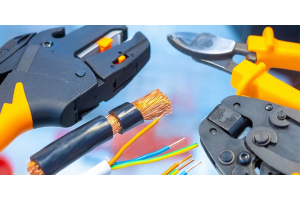
Crimp Tool: Used to crimp cable conductors to connector pins. Crimping tools usually come in different sizes to suit different types of connectors.
Stripping Tool: Used to strip the outer insulation of a cable to expose the conductor.
Torque Tool: Used to connect some connectors that need to be twisted to ensure proper connection and disconnection.
Receptacle Tool: Used to insert cables into receptacle type connectors.
Test Tools: Used to verify the electrical performance of the connection, including continuity testers, network analyzers, etc.
Mounting Fixtures: Some connectors may require special fixtures to ensure proper mounting and securing.
Glue and Insulation: used to secure insulation and protect the connection.
Connector manufacturers often provide detailed connector installation guides that contain installation procedures, tips, and precautions for specific connectors. It is important to read the manufacturer's guide carefully before installing a connector to ensure proper installation and avoid potential problems.

